

 A Bulbs
 Deco Bulbs
 Filament Bulbs
 High Watt Bulbs
 Spot Lamps
 Others
 Downlights
 Spotlights
 Panel Lights
 Flood Lights
 Street Lights
 LED strip lights
In LED bulb manufacturing, SKD stands for Semi-Knocked Down. Rather than shipping a fully assembled bulb, the supplier provides a combination of parts and subassemblies for final assembly at a local plant. There is no standard SKD package, so both sides need to agree on what will be supplied, what has already been assembled, and what work will be completed locally.
That distinction matters because the boundary determines which drawings, process controls, inspections, equipment, and traceability records each party needs. A useful SKD plan therefore begins with a controlled product definition, not with a loose parts list. Using the WELLMAX Classic Series LED Bulb as an example, this guide explains how to define the scope of an SKD project.
How Does SKD Work in LED Bulb Manufacturing?
An SKD package can include individual parts, pre-assembled modules, or both. The exact combination depends on the project. Some items may arrive ready for final assembly, while others may still require local processing or testing. For this reason, the term “SKD” alone is not enough. The project documents should clearly state what is supplied, what has already been completed, and what the local assembly plant is responsible for.
For practical purposes, an SKD LED bulb should be defined by the approved bill of materials and process boundary for a specific product version. The project documents should identify every supplied item, its revision, its assembly state, and the party responsible for the next operation. Without those details, two teams can use the same term while expecting different deliveries.
The Four Key Records That Define the SKD Boundary
A controlled SKD project needs four key records that agree with one another. Each answers a different question.
- The bill of materials identifies the approved items and quantities for the selected configuration.
- Drawings and specifications define dimensions, materials, interfaces, ratings, and acceptance criteria.
- The process flow assigns assembly and inspection operations to the supplier side or the local plant.
- The approved sample provides a physical reference for appearance and fit where written criteria alone are insufficient.
These records should carry product and revision identifiers. A picture or generic component name cannot replace them. For example, “driver” does not reveal its electrical rating, geometry, connector arrangement, or revision. “Housing” does not define the material, dimensions, or interface with the cover and lamp base.
Use One Approved Configuration as the Control Reference
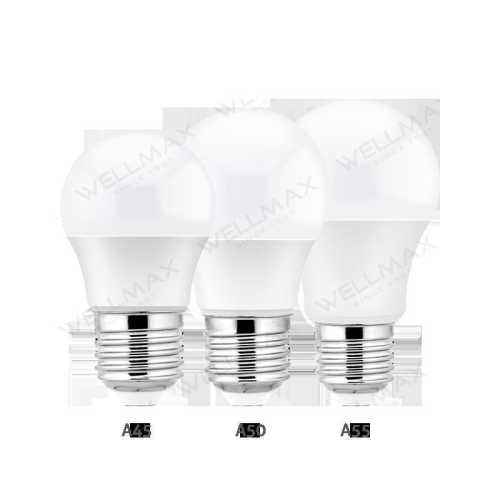
Our WELLMAX Classic Series LED Bulb provides a useful example of why configuration control comes before local assembly. The series includes multiple wattage and market configurations and uses a thermally conductive plastic body with a PC cover. Those facts define a product family, but they do not define one SKD shipment.
For an SKD project, the team must select one approved Classic Series configuration and bind its wattage, electrical input, lumen output, dimensions, lamp base, material references, market requirements, and revision to the relevant BOM and process records. The Classic Series identifies the product family, but the controlled project file must identify the configuration actually being assembled.
This prevents a common error: combining a housing from one configuration, a driver reference from another, and packaging or markings from a third because all carry the same family name. Family membership is not interchangeability. Compatibility requires documented approval at the configuration level.
Map Interfaces, Not Just Parts
A parts list says what exists; an interface map says what must work together. For an LED bulb, the critical interfaces normally include the electrical connection between the driver and LED module, the mechanical fit among the cover, housing, and lamp base, and the thermal path from heat-generating components to the housing and surrounding structure.
Each interface creates a control question. Can the parts be connected without reversing polarity or damaging conductors? Do mating dimensions and tolerances allow repeatable assembly? Does the assembled structure preserve the intended thermal contact? Does the chosen joining method resist movement during handling? The project documents must convert those questions into measurable characteristics and defined checks.
This is why replacing one item with a visually similar part is not a minor purchasing decision. A change can alter electrical behavior, fit, thermal performance, or the status of compliance documents. Any such change should undergo formal review before entering production.
Separate Supplier and Local-Assembly Responsibilities
Responsibility should be assigned by operation and characteristic, not by a vague statement that one side “handles quality.” A practical matrix names the owner of each activity, the record produced, and the action required when a result is outside the approved limit.
| Control point | Supplier-side responsibility | Local-assembly responsibility |
| Product definition | Release approved item and revision data | Confirm received data match the scheduled build |
| Incoming condition | Protect and identify supplied parts | Inspect identity, quantity, condition, and sampled characteristics |
| Assembly process | Provide the agreed process requirements | Control operators, equipment, settings, and work instructions |
| In-process checks | Define supplied-module evidence where applicable | Record checks at the assigned assembly stages |
| Final verification | Supply agreed reference data | Test the finished product against the approved specification |
| Traceability | Preserve lot and revision identity before shipment | Link incoming lots to production and finished-product records |
The exact allocation varies by project. What should remain constant is the absence of unowned steps. If a characteristic can fail but neither side is assigned to verify it, the SKD boundary has a control gap.
Incoming Inspection: Confirm Identity Before Assembly
Incoming inspection should first answer whether the received material is the material that was approved. Labels, item codes, revision identifiers, quantities, packaging condition, and lot references establish identity and traceability. Visual condition and sampled measurements can then detect shipping damage or variation in critical characteristics.
Sampling plans and acceptance limits must come from the project’s quality plan. They should reflect the risk of the characteristic, supplier history, lot size, and the consequences of a missed defect. A generic inspection percentage is not a substitute for this decision. Safety-related, electrical, mechanical, and cosmetic characteristics may justify different controls.
Quarantined material should remain physically segregated, and its status should be clearly controlled in the inventory or quality system. The disposition record should show whether the material was returned, reworked under approval, or accepted through a documented concession. This prevents an unresolved lot from re-entering production without a decision trail.
In-Process Control: Stabilize the Local Operation
Local assembly adds process variation, so inspection at the end cannot be the only control. Work instructions should define the sequence, tools, settings, handling rules, and inspection points for the agreed configuration. Operators need a clear method for recognizing the current product revision and stopping work when parts or results do not match it.
Useful in-process checks are placed where a defect can still be isolated and corrected. Depending on the approved process, they may cover connection integrity, polarity, fastening or joining conditions, dimensional fit, surface condition, and identification. The actual characteristics and limits must be derived from the product documents and validated process, not copied from another bulb.
Equipment settings also need control. A recorded setting is meaningful only when the equipment is identified, maintained, and checked with an appropriate method. When a tool, fixture, or process changes, the team should evaluate whether the existing result remains valid.
Final Verification Covers More Than Power-On
A bulb that turns on has passed only a basic functional observation. Final verification should address the characteristics promised by the approved product specification. These commonly fall into four groups.
Electrical checks evaluate the agreed operating characteristics and screen for unsafe or abnormal behavior. Photometric checks evaluate lumen output and other declared optical characteristics under the stated test conditions. Mechanical checks examine assembly integrity, dimensions, lamp-base fit, marking, and visible workmanship. Thermal evaluation examines whether the assembled construction behaves within the approved thermal design under the defined operating conditions.
Lumen output and perceived brightness must not be treated as synonyms. Lumen output is a measured quantity. Perceived brightness also depends on distribution, surroundings, adaptation, color characteristics, and the observer. A visual impression cannot replace a photometric result, and a lumen value should be compared only when the test basis is understood.
The final record should identify the tested product version, lot, equipment or method, date, result, and disposition. A pass label without traceable data offers little help when a later investigation needs to distinguish one batch from another.
Traceability Turns Records Into a Usable History
Traceability should connect incoming lots, local production batches, process records, inspection results, and finished-product identification. The purpose is not paperwork volume. It is the ability to answer a focused question: which finished units may be affected by a specific material, process condition, or revision?
A useful traceability system uses identifiers that remain readable and consistent across physical labels and digital records. It also defines retention, access, and correction rules. When a record is amended, the original entry, reason, date, and responsible person should remain visible.
Change Control Protects the Approved Configuration
SKD programs often involve local sourcing, substitute materials, equipment adjustments, or packaging changes. Each proposed change should be screened for effects on electrical, photometric, mechanical, thermal, marking, and compliance requirements. The depth of validation should match the risk of the change.
Approval must occur before routine use. The revised item, documents, sample status, effective date, and affected inventory should then be coordinated. Otherwise, an old drawing, new part, and earlier inspection plan can coexist on the same production line.
Common SKD Misunderstandings
SKD is not a fixed percentage of disassembly. A percentage does not explain which interfaces or operations remain local.
SKD is not merely a shipping format. It changes process ownership, equipment needs, competence requirements, inspection stages, and record control.
A finished sample is not the whole specification. It supports comparison, but it cannot communicate hidden electrical characteristics, material grades, revision history, or test conditions by itself.
Final inspection cannot repair an unstable process. It may detect some defects, but prevention depends on controlled materials, defined operations, capable equipment, trained operators, and timely in-process checks.
Conclusion
SKD in an LED bulb means that an agreed set of parts and subassemblies is supplied for local assembly. The term becomes operational only when a specific product configuration, BOM, drawings, assembly boundary, responsibility matrix, inspection plan, and traceability method are aligned.
For the Classic Series LED Bulb, the product-family page is a starting reference, not an SKD definition. A project should freeze one configuration, map its interfaces, assign every control point, verify the finished result against approved criteria, and review changes before use. That approach makes SKD a controlled production model rather than an ambiguous list of parts.
Frequently Asked Questions
Does SKD always contain the same LED bulb parts?
No. The supplied parts and subassemblies depend on the agreed project boundary. The approved BOM, drawings, process flow, and version records define the contents.
What is the difference between an SKD LED bulb package and a finished LED bulb?
A finished bulb has completed its defined assembly before shipment. An SKD package leaves agreed operations for the local plant, which also assumes the corresponding process-control and verification responsibilities.
Is a BOM enough to manage an SKD project?
No. A BOM identifies items, but the project also needs specifications, interface requirements, process ownership, inspection criteria, traceability, and change control.
Why must one Classic Series configuration be frozen?
The family contains configuration differences. Freezing one approved version prevents parts, ratings, dimensions, markings, and process requirements from being mixed across variants.